The autopilot has a limited error checking function, running on the secondary PPM encoder processor, which is designed to:
Detect complete loss of RC signal (if the RC receiver is able to generate a predictable signal-loss behaviour) and initiate a defined auto-mode response, such as returning to home. (Only some RC equipment is capable of this.)
The autopilot error checking cannot:
Detect if one more individual RC channel has failed or become disconnected
Detect if you’re flying too far away or are about to hit the ground
Detect autopilot hardware failures, such as low-power brownouts or in-air reboots
Detect if the autopilot software is not operating correctly
Detect other problems with the aircraft, such as motor failures.
Otherwise stop you from making setup or flight mistakes
Setting up Non-Normal Flight Modes
There are five completely different non-normal flight modes. In the order prioritised by the autopilot, these modes are: From most important to least important;
Critical Battery
RC and C2 Link (equal priority)
GNSS
Geofence
Critical Battery
The autopilot is fitted with a voltage and current sensor. Therefore, the autopilot is able to monitor the battery voltages and calculate the percentage of the battery capacity used. This enables the autopilot to activate the battery failsafe routine.
This is triggered when the flight battery voltage drops below a predefined critical voltage or the battery capacity used exceeds the warning capacity.
When battery critical is triggered, the autopilot sends a message to Neuron GCS via the telemetry link. Neuron GCS will then display the advisory “Battery Critical Landing” on the PFD. An audio advisory will also be given. Phase 2 will trigger the autopilot to go RTL flight and autoland. If the aircraft is within two metres of the launch position or does not have a GNSS lock, the aircraft will skip the RTL mode and land at its current position.
RC Link
Your RC transmitter outputs a PWM signal that is captured by your receiver and relayed to the autopilot. Each channel on your transmitter has a PWM range usually between 1100 – 1900 with 1500 being its neutral position. When you start your radio calibration on Neuron GCS, all your values will be at 1500. By moving your sticks, knobs and switches you will set your PWM range for each channel. The autopilot monitors your throttle channel and if notices a drop lower than FS_THR_VALUE (Default is 950) it will trigger the non-normal mode.
RC transmitters usually have a default range for each channel that goes from -100% to 100%, however most transmitters will allow you to extend this to -150% and 150% respectively. In the default setup, bringing your throttle to -100% will translate to a value close to 1100 and bringing it to -150% will translate to a value closer to 900. What we want to achieve is to let your receiver know that the throttle can go as low as -150% but keep the autopilot control range between -100% and 100%. Meaning that when flying, our throttle values will range between 1100 – 1900.
If we lose RC communication, the receiver if set up properly, will drop to the lowest known throttle value of ~900. This value falls below the FS_THR_VALUE and will trigger the autopilot to go into a non-normal mode if the throttle failsafe parameter (FS_THR_ENABLE) is enabled.
If the aircraft is < 2m from the launch position or the aircraft does not have a GNSS lock the aircraft will execute a landing at its current position
If the aircraft is > 2m from the launch position and has a GNSS lock, the aircraft will switch to RTL mode and then land at the launch position.
C2 Link
When flying in NAV mode, the autopilot is triggered into the non-normal mode if it loses the command and control (C2) link. In the event that the autopilot stops receiving MAVlink (telemetry protocol) heartbeat messages for more than 5 sec, the GCS non-normal (FS_GCS_ENABLE, 0=Disabled, 1=Enabled) will trigger the autopilot to change the flight mode to RTL and autoland. If the aircraft is within two metres of the launch position or does not have a GNSS lock, the aircraft will skip the RTL mode and land at its current position.
Note: This non-normal will not trigger in Stabilise mode.
GNSS
The aircraft uses a GNSS satellite receiver to locate the aircraft laterally. In the event that the GNSS system fails or insufficient satellites are in view, the autopilot will send a message to Neuron GCS. Neuron GCS will then display the warning “GPS Lost” on the PFD. If the aircraft is in NAV mode, the autopilot will select Height Hold as the flight mode ready for the co-pilot to recover the aircraft.
Geofence Non-Normal
The MultiRotor has a simple “tin can” shaped fence centred on home that will attempt to stop the vehicle from flying too far away. The maximum circular distance and height and the vehicle response when the fence is breached can be configured using Neuron GCS.
If the vehicle strays outside the fence it will switch into Return to Launch (RTL) mode. At the moment the fence is breached a backup fence is erected 20m further out (or up). If the vehicle breaches this backup fence (for example if the vehicle is not set up correctly or the operator takes control but is unable to bring it back towards home) RTL mode will be selected again (and another backup fence an additional 20m further out will be created).
A maximum of five back up fences will be created. Therefore, if the vehicle eventually flies 100m outside the original fence distance, the vehicle will switch into LAND mode. The assumption is that it’s impossible to get the vehicle home so best to just bring it down. The pilot can still retake control with the flight mode switches. Like with the earlier fences, another fence is erected 20m out which will again switch the vehicle to LAND if it continues away from home.
Refer to the appropriate Neuron GCS manual for information regarding the configuration and use of a Geofence.
Tips for the use of Geo-Fencing
GeoFencing should be disabled (i.e. Turned Off) when on the ground and for take-off. Be careful not to enable it on the ground, as it may declare a fence breach and try to fly to the return point.
Before flying with geo-fencing enabled make sure all the parameters are setup as described previously, and also make sure there are sufficient satellites in view (minimum seven (7) as indicated by GPS annunciation on PFD). If GNSS is lost Geo-Fencing will disable itself until functionality is regained. For this reason don’t use Geo-Fencing if the GPS signal is marginal.
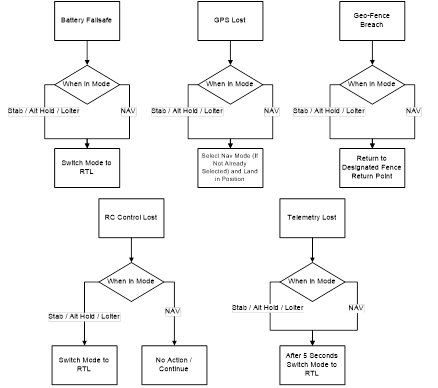
Process Flow
The Flowchart of the failsafes are included below. No one procedure overrides the other, and will take action on the most recent event.
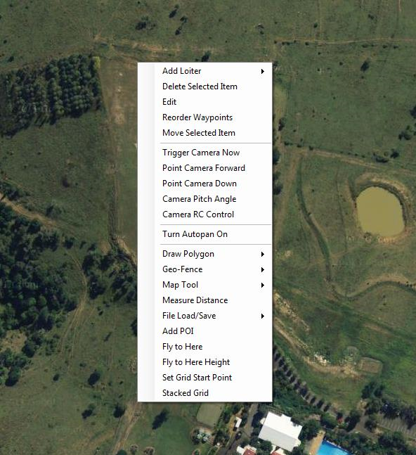
The camera gimbal is by default, controlled by the RC transmitter. However, some control functionality is offered through Neuron GCS.
On the map right-click menu there are five (5) options that can be selected to control the camera and the camera gimbal.
Action
Effect
Trigger Camera Now
Commands the camera to take a picture.
Point Camera Forward
Points the camera to the front of the aircraft. (The RC controller no longer has control) Note: For servo powered gimbals, stabilisation will no longer work in this mode.
Point Camera Down
Points the camera towards the ground. (The RC controller no longer has control) Note: For servo powered gimbals, stabilisation will no longer work in this mode.
Camera Pitch Angle
Commands the camera to pitch by a custom angle. (The RC controller no longer has control) Note: For servo powered gimbals, stabilisation will no longer work in this mode.
Camera RC Control
Hands the gimbal control back to the RC controller.
Lift the arm holding the motors until it clicks into place on the arm folding mechanism.
Propellers
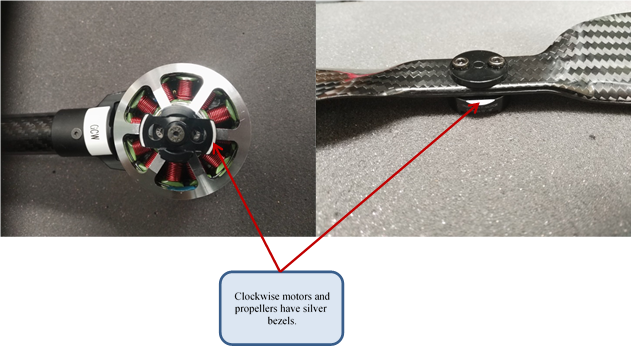
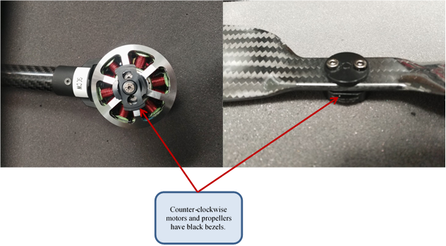
The propellers are fitted to the aircraft using a quick release system. Clockwise and counter-clockwise propellers are fitted with different quick release mounts that prevent propellers being attached in the incorrect position. The correct propeller for each motor can be identified by looking at the colour of bezel on both the motor and propeller side of the adapter. Clockwise motors and propellers have a silver bezel, and counter-clockwise motors and propellers have a black bezel.
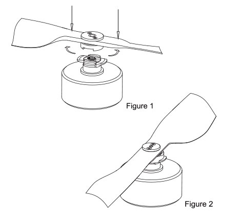
To attach the propeller to the motor, press the propeller down so that the locking plate is pushed to the bottom of the adapter. When the propeller is pushed all the way down, rotate the propeller 90 degrees in either direction until the locking plate springs up into the keyed slots on the propellers side of the adapter. Make sure that the locking plate goes all the way to the top of the keyed slot to ensure a proper lock.
Figure 18, Attaching the propeller
To remove the propeller, push the locking plate downwards and rotate the propeller by 90 degrees.
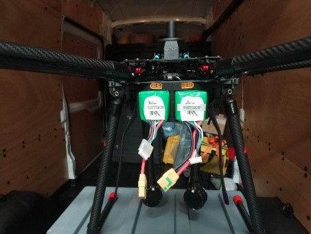
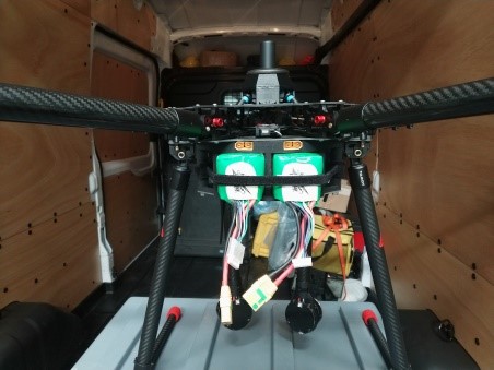
Battery
Installation
Slide the batteries into the battery compartments underneath the airframe. Use the two Velcro straps on either side of the aircraft to secure the batteries from sliding out in flight.
Charging
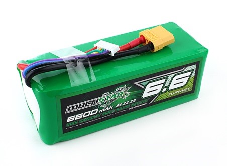
Characteristic
Value
Type
Lithium Polymer
Cell Configuration
6 Series – 1 Parallel
Voltage
22.2 V Nominal
Discharge Connector
XT90 – Spark Suppressant
Balance Connector
JST-XH
Weight
794 grams
Dimensions
143 x 50 x 53mm
Discharge Rate
10C (66A) Constant 20C (132A) Burst (10Sec)
Figure 19, Power Pack
YOU MUST READ THESE SAFETY INSTRUCTIONS, CAUTION AND WARNING BEFORE USING OR CHARGING BATTERIES.
LITHIUM BATTERIES ARE VOLATILE. FAILURE TO READ AND FOLLOW THESE INSTRUCTIONS MAY RESULT IN FIRE, PERSONAL INJURY AND DAMAGE TO PROPERTY IF CHARGED OR USED IMPROPERLY
Cautions
INFORMATION IN THIS DATA SHEET IS COMPILED USING THE OEM GUIDELINES
USE LITHIUM POLYMER SPECIFIC CHARGERS ONLY. DO NOT USE A NICKEL CADMIUM OR NICKEL METAL HYDRIDE CHARGER – FAILURE TO DO SO MAY CAUSE A FIRE, WHICH MAY RESULT IN PERSONAL INJURY AND PROPERTY DAMAGE.
NEVER CHARGE BATTERIES UNATTENDED. WHEN CHARGING LIPO BATTERIES YOU SHOULD ALWAYS REMAIN IN CONSTANT OBSERVATION TO MONITOR THE CHARGING PROCESS AND REACT TO POTENTIAL PROBLEMS THAT MAY OCCUR
SOME LIPO CHARGERS ON THE MARKET MAY HAVE TECHNICAL DEFICIENCIES THAT MAY CAUSE THEM TO CHARGE LIPO BATTERIES INCORRECTLY. IT IS SOLELY THE RESPONSIBILITY OF THE USER TO ASSURE THAT THE CHARGER USED WORKS PROPERLY.
IF AT ANY TIME YOU WITNESS A BATTERY STARTING TO BALLOON OR SWELL UP, DISCONTINUE THE CHARGING PROCESS IMMEDIATELY. DISCONNECT THE BATTERY AND PLACE IT IN A SAFE OBSERVATION AREA FOR APPROXIMATELY 15 MINUTES. CONTINUING TO CHARGE A BATTERY THAT HAS BEGUN TO SWELL WILL RESULT IN A FIRE.
BATTERY OBSERVATION SHOULD OCCUR IN A SAFE AREA OUTSIDE OF ANY BUILDING OR VEHICLE AND AWAY FROM ANY COMBUSTIBLE MATERIAL.
SHORTS CAN CAUSE FIRES! IF YOU ACCIDENTALLY SHORT THE WIRES THE BATTERY MUST BE PLACED IN A SAFE AREA FOR OBSERVATION FOR APPROXIMATELY 15 MINUTES. ADDITIONALLY, BE MINDFUL OF THE BURN DANGER THAT MAY OCCUR DUE TO A SHORT ACROSS JEWELLERY (SUCH AS RINGS ON YOUR FINGERS).
CHEMICAL REACTIONS ARE NOT INSTANTANEOUS; A BATTERY THAT HAS BEEN SHORTED MAY NOT IGNITE FOR 10 MINUTES.
ALL CRASH BATTERIES, EVEN IF NOT DEFORMED, SHOULD BE PLACED IN A SAFE AREA FOR OBSERVATION FOR AT LEAST 15 MINUTES.
IF FOR ANY REASON YOU NEED TO CUT THE TERMINAL WIRES, CUT EACH WIRE SEPARATELY, ENSURING THE WIRES DO NOT BECOME SHORTED ACROSS THE CUTTING TOOL
NEVER STORE OR CHARGE A BATTERY PACK INSIDE YOUR CAR IF THE INTERNAL TEMPERATURE WILL EXCEED 40 DEGREES CELSIUS.
Normal Charging
The charge rate should not exceed 1C (1 x the capacity of the battery, unless otherwise noted). Higher setting may cause problems which can result in fire.
For example: Charge a 730mAh battery at or below 0.73Amps. Charge a 5000mAh battery at or below 5Amps.
LiPo packs with balancing connectors must be used with balancers for safer charging.
To charge at greater than 1C (no more than 2C): You must use an approved charger in conjunction with a Balancer. Charging higher than 1C will reduce the cycle life.
To charge two packs in series: The packs need to first be charged individually and balancer used to ensure packs are matched. Only matched packs may be charged in series.( If all the voltages are within 0.01V of each other) Please note that this requires a “Y” cable be made to electrically attach the packs together in series and that the battery on the negative most side of this cable (the lead that goes to the negative terminal of the charger).
Storage and Transportation
Store batteries at room temperature between 8 and 25 degrees °C for best results.
If storing longer than one week; batteries must be stored at 3.8V/cell (60% charged).
Do not expose battery packs to direct sunlight (heat) for extended periods.
When transporting or temporarily storing in a vehicle, temperature range should be greater than 8 degrees °C but no more than 40 degrees °C.
Storing LiPo batteries at temperatures greater than 40 degrees °C for extended periods of time (more than 2 hours) may cause damage to battery and possible fire.
Battery Care
Only charge a LiPo battery with a good quality Lithium Polymer charger. A poor quality charger can be dangerous. Balancers are also recommended.
Set voltage and current correctly (failure to do so can cause fire).
Please check pack voltage after the first charge.
For example; a 6 Cell battery should measure 25.2V (24.9 to 25.32).
Do not discharge a battery to a level below 3V per cell under load. Discharging below 3V per cell can deteriorate battery performance. Be sure to set your ESC for the proper cut off voltage (18.0V cut off for 6S packs).
Use caution to avoid puncture of the battery. Puncturing a LiPo battery may cause a fire.
Operating Temperature:
Before flight: 8 to 40 degrees °C
Charge: 8 to 40 degrees °C
Discharge: 8 to 40 degrees °C
Always allow a battery to cool down to ambient temperature before re-charging.
During discharge and handling of batteries, do not exceed 40 degrees.
Battery Life
Batteries that lose 20% of their capacity must be removed from service and disposed of properly.
Discharge the battery to 3V/Cell, making sure output wires are insulated and then wrap battery in a bag for disposal
Battery Emergency Procedures
In the event of a battery swelling, conduct the following:
Cease charging immediately
Disconnect terminals
Completely Discharge Battery to 0.0V/Cell
Using wire cutters, cut terminals off battery
Submerge batteries in a solution of salt and water for 1 hour
Empty water following applicable waste management procedures
Dispose of batteries following applicable waste management procedures.
In the event of a battery fire, conduct the following:
If safe, isolate power to battery
Segregate battery from flammable surrounds, preferably in bucket of sand or LiPo bag.
Control fire using fire extinguisher
Dispose of batteries following applicable waste management procedures.
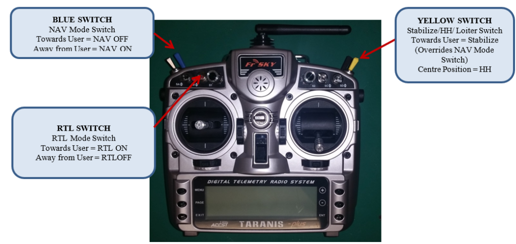
It is now necessary to set up the Stabilise/HH/POS/NAV/RTL switches functionality for the system. This utilises the following THREE switches on the transmitter. Switch on the transmitter.
Figure 14, Flight Mode Selector Switch
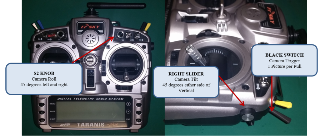
The system also has controls for manipulating the camera. They are located as follows:
Figure 15, Camera Controls
MultiRotor Flight Modes
MODE
ANNUNCIATION
DESCRIPTION
YELLOW SWITCH
BLUE SWITCH
RED SWITCH
Stabilise
STAB
The pilot’s roll and pitch input control the attitude of the MultiRotor. When the pilot neutralises the roll and pitch sticks the vehicle automatically levels itself (As trimmed). The pilot will need to regularly input roll and pitch commands to keep station in the prevailing environmental conditions (position and height). The pilot’s yaw input controls the rate of change of the heading. When the pilot neutralises the yaw stick the vehicle will maintain its current heading. The pilot’s power input controls the average motor speed meaning that constant adjustment of the power lever is required to maintain height. If the pilots sets zero power, the motors will stop and the vehicle will descend with no attitude control. The commanded thrust is automatically adjusted based on the attitude of the vehicle (i.e. increases as the vehicle experiences higher angles of bank and pitch) to reduce the compensation the pilot must do.
STAB
No dependency. Operation preference is NAV OFF
RTL OFF
Height Hold
HH
When height hold is selected, the power is automatically scheduled to maintain the vehicle’s current height. Pilot control inputs are required to maintain station. (i.e hover) or manoeuvre.
HH
NAV OFF
RTL OFF
Loiter
Loiter
Loiter mode automatically attempts to maintain the current location, heading and altitude. The pilot may fly the copter in Loiter mode as if it were in manual. Releasing the sticks will continue to hold position.
Loiter
NAV OFF
RTL OFF
Navigation Mode
NAV
GNSS coupled to autopilot to command flight path laterally and vertically according to active flight plan.
Loiter
NAV ON
RTL OFF
Return To Launch
RTL
When RTL mode is selected, the MultiRotor will return to the launch location. The vehicle will climb to a specified height if operating below, otherwise it will maintain current height. Once arrived at the launch position the vehicle will hover for a specified time (typically five (5) seconds before automatically landing.
No Dependency
No Dependency
RTL ON
Table 1, MultiRotor Flight Modes
MultiRotor Camera Controls
MODE
DESCRIPTION
BLBL
ROLL KNOB
PAN KNOB
RIGHT SLIDER
Camera Roll
The roll knob is used to control the roll angle of the camera. The range of motion is from 20 degrees left to 20 degrees right.
No Dependency
20 degree movement
No Dependency
No Dependency
Camera Tilt
The right slider is used to control the tilt angle of the camera. The range of motion is from horizontally forward to vertically down.
No Dependency
No Dependency
No Dependency
90 degree movement
Camera Pan
The pan knob is used to control the pan speed of the camera. The range of motion was 360 degree continuous rotation.
No Dependency
No Dependency
360 degree continuous pan
No Dependency
Camera Trigger
When the black switch is pulled, the camera will take a photo. If the switch is activated too fast (faster than 1 per 2 seconds) the camera may not take the pictures fast enough. If the switch is pulled and held on, the camera will only take 1 picture (unless camera is set to burst mode).
Aircraft (with all on-board equipment in place and functioning properly)
Aircraft battery pack (charged)
GCS Laptop (charged)
Antenna, and power cables
Peripheral interface equipment (mouse)
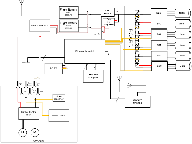
Avionics Block Diagram
The autopilot system can be divided into either airborne components or ground station components. The airborne components are referred to as the avionics. The avionics consist of the autopilot, GPS, RC receiver, and digital modem. Figure 5 shows avionics block diagram.
Figure 5, Aircraft System Architecture
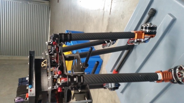
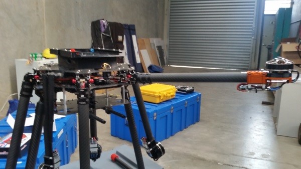
Air Vehicle
The Multirotor airframe is the casing that holds all of the system components. It is powered by four electric motors. The electric motors are powered by a Lithium Polymer (LiPo) battery.
The aircraft has the following characteristics:
Item
Hornet Multirotor
Airframe
Take-Off Weight
6.5 kg (2 batteries with payload) + 1.6 kg (4 batteries installed) 15kg MTOW
An autopilot is in reality a dedicated microprocessor that executes a preset program.
Understanding that the autopilot simply follows a preset program necessarily means that the onus is on the operator to understand how the program works. This manual describes how to prepare the aircraft for flight.
This guide is not intended for the inexperienced, and assumes a basic level of familiarity with both the equipment and the principles and requirements for autonomous flight.
This guide has been designed to provide step-by-step instruction for equipment and ground operations specific to the MultiRotor platform.
The first priority of anyone involved with unmanned aircraft is:
Safety!
Accidents can – and do – happen! It is the duty of everyone associated with unmanned aircraft to be mindful of the risks to persons, property and the aircraft, and to take all necessary actions to minimise those risks. Unmanned aircraft contain hazardous components, charged batteries, and spinning propellers, all of which represent a risk, not only to the pilot, but also to people in near proximity!
Symbology
Throughout this document the following symbols have been used:
This symbol identifies a point of note. The information presented is considered important and something that the reader should be aware of.
This symbol identifies a warning.Take note of the information presented as if it is n not observed and the procedure or action is not carried out as directed there is a real possibility of possible harm or damage to persons and/or property. This symbol usually accompanies a description on how to do something.
This symbol identifies a hazard or critical factor.This symbol is used when there is a real and possible risk to persons and/or property.
Pay particular attention to the warnings contained in this manual. These warnings relate to real and present hazards, and include suggestions on ways to mitigate these hazards to an acceptable level.
Safety Warnings When Handling Powered Aircraft
The following must be observed in order to maintain the safety of personnel, equipment and property:
When powered, always assume that the aircraft is ARMED. Consider safety of personnel and surrounding environment when dealing with a powered aircraft.
Disconnect the ESC(s) from motor(s) and power cable(s) when working/maintaining aircraft for extended periods. This is to avoid damage to equipment and mitigate harm to personnel.
Avoid soft rebooting of the autopilot while the flight battery is attached. In some situations, the timer outputs can become corrupted, causing the motors to unexpectedly start.
Avoid connecting the Autopilot’s USB interface while the aircraft is powered.
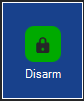
NEURON GCS incorporates an ARM and SAFE mode. When the aircraft is connected to NEURON, these modes can be set using the ARM and DISARM buttons located at the top right-side of the software’s MFD-style interface. These buttons are illustrated below.
ARM
Enables/Arms throttle control on UAV.
Will be greyed out if: UAV is NOT connected; orUAV is already ARMED
DISARM
Disarms throttle control on UAV.
Will be greyed out if: UAV is NOT connected; orUAV is already DISARMED
As noted in the table illustrated above, both buttons will be greyed-out if the aircraft is not connected to Neuron GCS:
When connected, the [DISARM] button will remain grey-out if the aircraft is already disarmed; at this state, the [ARM] button will be coloured, and ready to arm motor(s).
Else, the [ARM] button will remain grey-out if the aircraft is already armed; in this state, the [DISARM] button will be coloured, and ready to disarm motor(s).
WHEN ARMED IN SEMI-AUTONOMOUS (NAV) CONTROL, THE MOTOR MAY START AT ANY TIME.
WHEN ARMED, THE MOTOR MAY ALSO START, SHOULD THE THROTTLE CONTROL ON THE RC TRANSMITTER BE MOVED – EITHER ON PURPOSE OR ACCIDENTALLY!
Never pick up the aircraft and the radio controller at the same time. It is very easy to bump the throttle and inadvertently cause the motor to start spinning.
Never fly with a battery that has a low state of charge. This may lead to a crash.
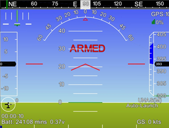
WHEN THE WORD ‘ARMED’ APPEARS IN THE PFD; OR IF THERE IS NO WORD IS DISPLAYED – THE AIRCRAFT MOTOR(S) IS/ARE IN ARMED STATE.
Figure 1 (a) ARMED displayed on PFD, indicating aircraft motor(s) is/are set in an armed state.
Figure 1 (b) After the 10 seconds, the word ‘ARMED’ will no longer be displayed on the PFD.
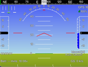
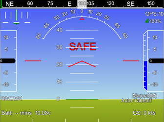
‘SAFE’ will be displayed in the PFD to indicate that the aircraft is in a disarmed state, and safe to handle without risk of motor spin-up.
Figure 2, SAFE displayed on PFD, indicating aircraft motor(s) is/are set in a disarmed state.
This record of revisions contains all changes made to the V-TOL Pty. Ltd. HORNET MULTIROTOR FLIGHT MANUAL. Changes to this manual are listed in the following table. Ensure all HORNET MULTIROTOR FLIGHT MANUAL copies at all locations are updated, with superseded pages removed and replaced as required and old pages taken out of usage as applicable.
Revision Number
Section Revised
Revision Issued Date
Revised By
1.0
Initial Issue
29/10/2015
Andrew Rieker
2.0
Revised Neuron Operations
14/04/2016
Luke Horwood + Andrew Rieker
2.1
Update Schematic correct inaccuracies in switch dependencies