The autopilot has a limited error checking function, running on the secondary PPM encoder processor, which is designed to:
- Detect complete loss of RC signal (if the RC receiver is able to generate a predictable signal-loss behaviour) and initiate a defined auto-mode response, such as returning to home. (Only some RC equipment is capable of this.)
The autopilot error checking cannot:
- Detect if one more individual RC channel has failed or become disconnected
- Detect if you’re flying too far away or are about to hit the ground
- Detect autopilot hardware failures, such as low-power brownouts or in-air reboots
- Detect if the autopilot software is not operating correctly
- Detect other problems with the aircraft, such as motor failures.
- Otherwise stop you from making setup or flight mistakes
Setting up Non-Normal Flight Modes
There are five completely different non-normal flight modes. In the order prioritised by the autopilot, these modes are:
From most important to least important;
- Critical Battery
- RC and C2 Link (equal priority)
- GNSS
- Geofence
Critical Battery
The autopilot is fitted with a voltage and current sensor. Therefore, the autopilot is able to monitor the battery voltages and calculate the percentage of the battery capacity used. This enables the autopilot to activate the battery failsafe routine.
The battery non-normal is triggered when the flight battery voltage drops below a predefined critical voltage or the battery capacity used exceeds the warning capacity.
When the non-normal is triggered, the autopilot sends a message to Neuron GCS via the telemetry link. Neuron GCS will then display the advisory “Low Battery” on the PFD. An audio advisory will also be given. It will trigger the autopilot to go RTL flight mode.
RC Link
Your RC transmitter outputs a PWM signal that is captured by your receiver and relayed to the autopilot. Each channel on your transmitter has a PWM range usually between 1100 – 1900 with 1500 being its neutral position. When you start your radio calibration on Neuron GCS, all your values will be at 1500. By moving your sticks, knobs and switches you will set your PWM range for each channel. The autopilot monitors your throttle channel and if notices a drop lower than FS_THR_VALUE (Default is 950) it will trigger the non-normal mode.
RC transmitters usually have a default range for each channel that goes from -100% to 100%, however most transmitters will allow you to extend this to -150% and 150% respectively. In the default setup, bringing your throttle to -100% will translate to a value close to 1100 and bringing it to -150% will translate to a value closer to 900. What we want to achieve is to let your receiver know that the throttle can go as low as -150% but keep the autopilot control range between -100% and 100%. Meaning that when flying, our throttle values will range between 1100 – 1900.
- If we lose RC communication, the receiver if set up properly, will drop to the lowest known throttle value of ~900. This value falls below the FS_THR_VALUE and will trigger the autopilot to go into a non-normal mode if the throttle failsafe parameter (FS_THR_ENABLE) is enabled.
- The aircraft will switch to RTL mode and then land at the launch position.
C2 Link
When flying in NAV mode, the autopilot is triggered into the non-normal mode if it loses the command and control (C2) link. In the event that the autopilot stops receiving MAVlink (telemetry protocol) heartbeat messages for more than 10 sec, the GCS non-normal (FS_GCS_ENABLE, 0=Disabled, 1=Enabled) will trigger the autopilot to change the flight mode to RTLNote: This non-normal will not trigger in UNAS/FBW A mode.
GNSS
The aircraft uses a GNSS satellite receiver to locate the aircraft laterally. In the event that the GNSS system fails or insufficient satellites are in view, the autopilot will send a message to Neuron GCS. Neuron GCS will then display the warning “GPS Lost” on the PFD. If the aircraft is in NAV mode, the aircraft will attempt to navigate using its inertial sensors.
Geofence Non-Normal
A GeoFence is an imaginary boundary that can be set up to enclose a flight area. Picture a GeoFence as a fence around a property, but with one difference – it also has a floor and a ceiling! The concept is simple – while the aircraft remains completely within the GeoFence, all is well, and the mission will proceed as normal. Should however – for ANY reason – the aircraft ‘touch’ the GeoFence, the aircraft will automatically switch to NAV mode, and fly back to the GeoFence Return Point. Once at the return point the aircraft will loiter at that point awaiting the next command. This loiter is indefinite, until the next command is received.
Refer to the appropriate Neuron GCS manual for information regarding the configuration and use of a Geofence.
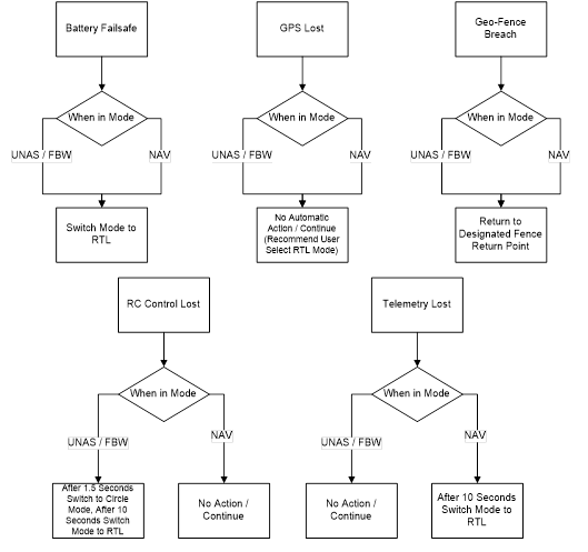
Process Flow
The Flowchart of the failsafes are included below. No one procedure overrides the other, and will take action on the most recent event.