01.09 Principles of Operation – Remote Pilot Station
Aim
At the end of this lesson, you should be able to correctly:
- Identify and described the purpose of various features of a remote pilot station:
- transmitter
- command and control link
- flight controls
- other controls
- antennas/aerials
- software, including firmware and updates
- telemetry
- non-payload communications
- power supply
The Remote Pilot Station
Remember – there is no such thing as a fully autonomous aircraft.
Such an aircraft would not require any human intervention at all to plan and execute a mission.
Aircraft that do require some form of human intervention must be able to communicate with the human – hence the need for a data link.
Most smaller unmanned aircraft have more than one form of data link operating simultaneously – each with its own dedicated function.
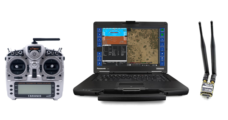
Common Components of the Remote Pilot (or Ground Control) Station typically include the following:
- 1x Ground Control Station (GCS) Computer/Laptop
- 1x Radio Control Transmitter (2x required if using a buddy box setup)
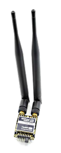
- 1x Radio telemetry – used for datalink between aircraft and GCS
Command & Control Link
A control link is responsible for sending signals from the remote pilot or GCS to the aircraft in order to directly govern the operation of the aircraft.
Feedback signals travel from the aircraft to the GCS to provide location, status, reports and warnings.
Auxiliary functions are controlled from the GCS. (Lights/sirens/dropping devices/cameras).
Examples of command & control links are:
- Link between the aircraft and GCS;
- Link between the aircraft and pilot’s manual remote control via Radio Transmitter; or
- A long-range link with GCS via a 5G data-link.
Note: A stable link between the aircraft and remote pilot station is critical for safe operation.
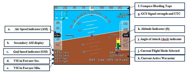
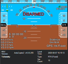
Example of flight critical feedback from a Command & Control Link is the Primary Flight Display (PFD), which shows in-flight information, such as:
- Altitude Indicator
- Airspeed Indicator (ASI)
- Ground Speed (GS)
- Vertical Speed Indicator (VSI)
Transmitter
There are several commercially available radio transmitter. These commonly have two (2) stick for the pilot’s flight control inputs,
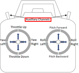
along with a number of toggle switches for additional control inputs, such as:
- Flight modes
- Landing gears
- Flaps
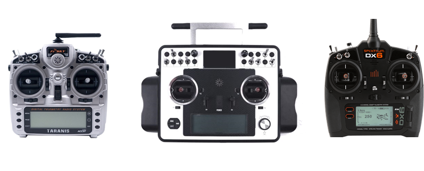
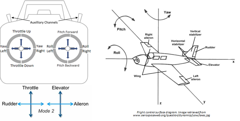
Commercial RC Transmitters may have different stick layouts. Diagrams below show a Mode 1 and Mode 2 stick layout, which inter-changes pitch and throttle.
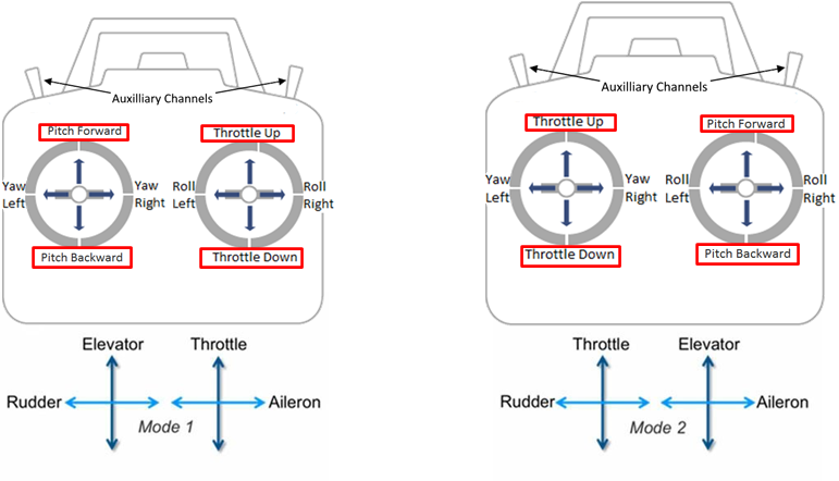
Flight Controls
Mode 2 more closely resembles manned aircraft controls, which typically has pitch and roll on the same stick. Below is a diagram illustrates stick input with relation to a fixed-wing control.
Other Controls
In addition to flight controls, other optional controls can be added, as dependant on aircraft configuration. These include, but are not limited to:
- Flaps
- Landing Gears
- Camera or payload Control
These additional controls can be configured on as switches on the transmitter or sent as commands directly from the GCS software.
Antennas & Aerials
Signal Strength & Directionality
The maximum power we can use to communicate with an unmanned aircraft is set by regulation – we have no choice with this. (Antennae gain is also factored into the regulations!)
Signal strength (received) is NOT just a function of transmitted power – antennae type (including directionality) also has a significant influence on received signal strength – in terms of both the transmitter and the receiver requirements!
Types of Antennas
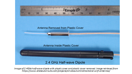
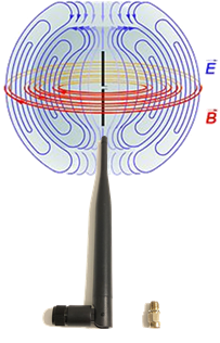
Antennas used in commercial UAVs are typically omnidirectional, which is
Dipole Waveform:
- Common frequencies are 2.4 GHz and 5 GHz
- Common wave lengths are:
- quarter-wave (¼)
- half-wave (½)
- full-wave
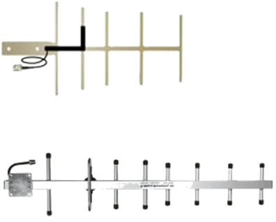
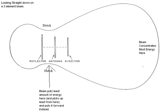
A Directional Antenna configurations are a series (or array) of dipole antenna, which are arranged in a way that propagates waves in a specific direction.
Software, Firmware, & Updates
Software
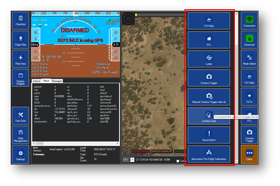
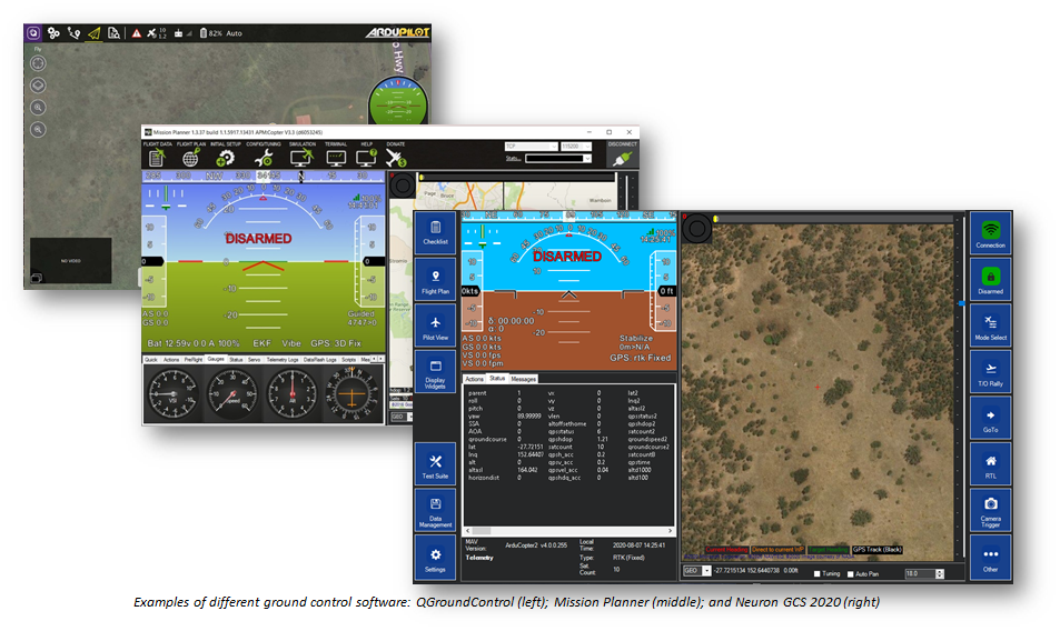
“Software” typically refers to the off-board program used to operate and monitor the aircraft from a remote station (Ground Control Station Software).
The main functions of a GCS Software is:
- To providing data, status and diagnostic feedback of the aircraft,
- To allow for control of aircraft state (ARMED or DISARMED), and
- To facilitate pre-flight planning
This is typically off-board, on the GCS, or an app on a mobile device used to connect with the aircraft.
Firmware
“Firmware” typically refers to the on-board program and flight-critical component, which governs the aircraft’s low-level control functions.
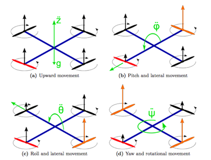
The on-board firmware interprets these control inputs send from the remote pilot station. The firmware then execute the appropriate flight control surfaces and/or throttle response to achieve the desired control inputs.
Examples below illustrates throttle control of individual motors on a Quad Multirotor configuration, which is typically governed by the on-board firmware.
Updates
Software and firmware versioning are typically shown with three (3) or more numbers.
Examples: v3.0.13
- The first no. indicates major changes to the software;
- The second no. indicates minor changes to the software;
- The third no. indicates patches to the software, typically for fixes to existing bugs.
Updates are a method for users to load new software or firmware onto our system:
- Software updates can usually be ran “in-place” without special considerations
- Firmware updates usually must be carefully selected as they influence the flight critical performance of the system
Key reasons to update are:
- To maintain software integrity, which may be affected by changes made to the computer’s operating system and/or hardware;
- To maintain software integrity against new or pre-existing software/firmware bugs;
- To maintain hardware compatibility with newer aircraft components and designs; and
- To generally to acquire newer features added by the software developer
Telemetry
Telemetry in the context of UAV operations, is the transfer or communication of data to and from remote points in a field. Telemetry is typically attached to the Ground Control Station, and the aircraft, to allow for communication between the two.
What sort of information do you think can be transmitted?
The cases where telemetry is unreliable:
- Only shows state of the aircraft at the specific time when it is sent
- Can be slow (low data rate) depending on link quality
- Might disconnect (if radio link disconnects)
Payload Communications
Similar to Command & Control Links, Payloads can be communicated via:
- Radio
- Cellular
- Satellite
Payload communication could be:
- “on-line”: meaning information is updated in real time to the GCS; or
- “off-line”: meaning information is stored securely on-board a payload system for later retrieval.
Examples of payload communications:
- Secure Integrated Airspace Management (SIAM): event data sent via LTE
- Survey camera: photos stored to SD card during flight
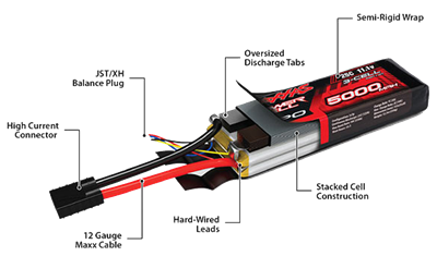
Power Supply
On-site operations:
- Power supplied by grid network; or
- Uninterrupted Power Supply (UPS)
Off-site operations:
- Battery banks
- Generators
Battery charging stations are usually set up to ensure continuous operations during extended flight day