Aim
To gain an understanding of the aeronautical documentation and charts that an pilot of an unmanned aircraft is required to understand when operating within Australia.
Objectives
At the end of this briefing you will be able to:
- Have a basic understanding of how to read aeronautical documents and charts.
- Understand the importance of correctly interpreting meteorological information before undertaking a mission.
- Use aeronautical documents to conduct desktop assessment of the viability of potential UAV operating sites.
Aeronautical Documents
Required Aeronautical Documents
- Charts
- Planning Chart – Australia
- Acronym: PCA
- Type: Lambert Conical Projection
- En-route Chart – Low
- Acronym: ERC-L
- Type: Lambert Conical Projection
- Visual Navigation Chart
- Acronym: VNC
- Type: Lambert Conical Projection
- Visual Terminal Chart
- Acronym: VTC
- Type: Mercator Projection
- Planning Chart – Australia
- En-route Supplement – Australia
- Notice to Airmen (NOTAM)
- Aeronautical Information Publication – Supplements & Information Circulars
Charts
Any point on the surface of the earth can be precisely referenced in terms of a latitude and longitude.
Meridians of longitude are half ‘great circles’, perpendicular to the equator, that extend from pole to pole. The meridians are identified by the angle that they subtend, at the centre of the Earth, with the prime meridian. That angle is measured in degrees, minutes and seconds east or west from the prime meridian – the Greenwich Observatory, England.
Parallels of latitude are circles drawn around the Earth starting from the equatorial plane, north and south of the equator and parallel with it and reducing in circumference toward the poles. For our purposes we can say that the parallels appearing on aviation charts are identified by the angle that they subtend with the equatorial plane, i.e. they are geodetic, measured in degrees, minutes and seconds and whether they lie north or south of the equator.
Measurements
One “nautical mile” is the length, at the Earth’s mean sea level surface, of one minute of arc of a great circle.
The International Nautical Mile is 1852 metres or 6076.1 feet. Consequently, one degree of latitude (measured along a meridian) has an equivalent surface distance of 60 nautical miles, and one second of latitude is about 31 metres, while 1/100th of a second is about 0.3 metres.
A “knot” is a speed of one nautical mile per hour.
Latttitude and longitude coordinates (“lat/long“) are expressed with the direction from the equator/prime meridian first (e.g. S and E), then numbers representing the degrees followed by numbers for the minutes. The symbols for degrees and minutes are omitted, e.g. S36 44.1 E147 10.2.
This is the standard format for geographic locations in ERSA.
Recommended VFR Charts – Planning Chart Australia
Planning Chart Australia (PCA) is designed to assist in initial VFR flight planning.
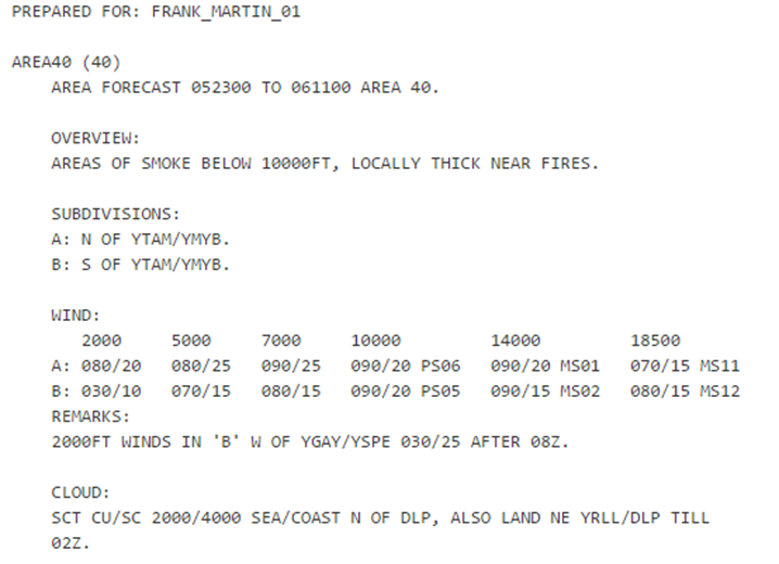
The PCA is a single sheet showing the coverage of the World Aeronautical Charts, the meteorological area forecast (ARFOR) boundaries, the estimated FIS VHF coverage from both 5000 feet AMSL and 10 000 feet (but not the frequencies), and the areas without FIS VHF coverage. The FIS HF communication frequencies are shown. The spot location of about 700 named airfields is indicated
PCA is designed to assist in initial VFR flight planning and it is amended semi-annually. It is of rather limited use in initial planning of flights below 5000 feet (i.e. most ultralight flights) in eastern Australia because straight-line tracks between departure point and destination may be precluded because of the topography, and there are no indications of such on the PCA.
Recommended VFR Charts – World Aeronautical Charts
The 43 Australian World Aeronautical Charts (WACs) are small scale (1:1,000,000 or 1mm=1km), derived from aerial photography, and designed for pre-flight planning and flight. They are part of an ICAO international series. They do not indicate Control Zone (CTR) or Prohibited, Restricted and Danger areas (PRD), nor is there any Flight Information Area (FIA), radio communications or radionavigation information.
Each WAC chart generally covers 6° of longitude and 4° of latitude. Sheet dimensions are about 70 × 60 cm and the scale is such that a real distance of one nautical mile is represented by less than 2 mm on the chart; thus WACs are really not suited to low-altitude navigation in slow aircraft.
Recommended VFR Charts – Visual Navigation Charts
Visual Navigation Charts (VNCs) are a larger scale (1:500,000) and show airspace information and FIS detail laid over the topographic base.
VNC charts contain the following airspace detail:
- CTR, CTA dimensions and lower levels.
- Flight Information Area and Surveillance Information Service boundaries where available.
- Flight Information Service and Surveillance Information Service frequencies and providers
- Communication and navigation aid frequencies for licensed airfields
- PRD and designated & remote areas.
There are only 15 VNCs, those available covering the more populous areas of Australia — Tasmania to North Queensland, plus areas around Perth, Adelaide, Darwin and Tindal.
Recommended VFR Charts – Visual Terminal Charts
Approximately 25 Visual Terminal Charts (VTCs) charts provide both aeronautical and topographic information around major airports at a scale of 1:250,000.
They are essential for VFR operations in the vicinity of such airports to avoid violating controlled airspace.
The charts are based on the NATMAP 250K series maps and use the Universal Transverse Mercator [UTM] projection but with a latitude/longitude graticule rather than the normal UTM grid
Their dimensions are around 90 × 50 cm and show the following details:
- PRD areas.
- CTR and associated CTA dimensions including the lower levels of the CTA steps surrounding the airport, lanes of entry, ATC check points.
- Surveillance Information Service frequencies where available.
- Communication and navigation aid frequencies for licensed airfields.
- VFR approach points.
Recommended VFR Charts – En Route Chart (Low-Level)
The En Route Chart (Low-Level) (ERCLO) series is drawn to various scales to accommodate significant air traffic route areas and shows controlled airspace, PRD areas, air routes and segment distances, ATS and radio-navigation services, ATS frequencies and location, plus communication and navigation aid frequencies for licensed airfields — but no topography.
It also indicates those airfields where VHF radio contact with FIS is possible from the ground.
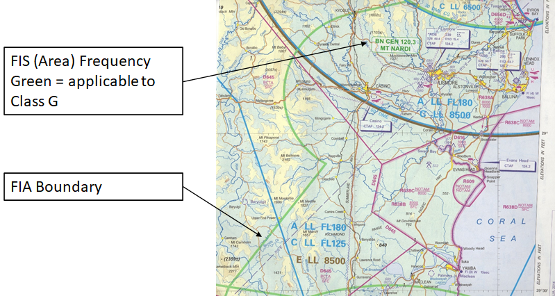
The FIS area boundaries are shown together with an information box showing the provider of the flight information service (e.g. Brisbane Centre), the frequency and the location of the area transceiver.
The series of eight sheets cover Australia and are intended primarily for IFR flights conducted below 20 000 feet.
Map Topography
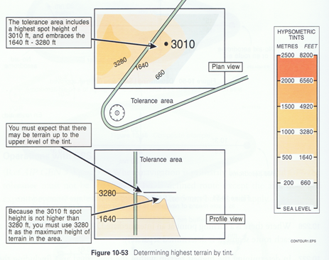
Aircraft operating under the VFR must navigate by visual reference to the ground. To assist this visualisation, WACs and VNCs display tinted topographic contours signifying surface areas between the 660 feet (200 m) and 1639 feet elevations, 1640+ feet (500 m), 3280+ feet (1000 m), 4920+ feet (1500 m) and 6560+ feet (2000 m) levels.
The shape of the contours and the width between them indicates the form of the land and the gradient. The closer the contour lines (i.e. the narrower the colour bands) are to each other, the steeper the gradient.
Recommended VFR Charts – WAC Chart Elevations
The WAC chart utilises relief shading of elevated ranges and ridges so that they are more evident.
Spot elevations are also shown and the highest spot elevation within each chart graticule is recorded in a bolder lettering than other spot elevations. The graticule on the WACs and VNCs is spaced at 30 minutes of latitude and 30 minutes of longitude.
The contours on VTCs are at 500+, 1000+, 2000+, 3000+, 4000+ and 5000+ feet amsl, but in addition all areas are shaded purple where there is less than 500 feet of clearance between the terrain and the lower limit of the overlying controlled airspace. Like WAC and VNC, the highest spot elevation within each chart graticule is shown in a bolder type than other spot elevations.
Recommended VFR Charts – WAC Chart Details
The VTCs generally cover an area within a 40–50 nm radius from the major airport and are the essential chart for visual navigation within that area.
Vegetation is usually not shown on WACs, nor are many structures except for towers and similar obstructions to low-flying aircraft; although grain silos — which are an excellent navigation aid usually associated with a railroad — are shown. Railroads, power transmission lines and some roads are depicted.
Wind Data
For all wind velocities, given in meteorological forecasts and actuals, the directions are relative to true north, except if you happen to hear a broadcast from a CTR tower controller (or an Automatic Terminal Information System [ATIS] broadcast). These systems provide the wind direction as magnetic, because the airfield runway numbers are relative to magnetic north. The air route directions shown on ERC-L are also relative to magnetic north.
Universal Time
Time is important for aerial navigation.
The reference time is Universal Coordinated Time (symbol) rather than local time.
The suffix ‘Z’ is used to identify dates and times as UTC, so it may be referred to as ‘Zulu’ time — the phonetic for ‘Z’.
UTC and the 24-hour clock system — rather than local time — are used throughout the aviation information, communication and meteorological services.
(UTC is 10 hours behind Australian Eastern Standard Time – Add an additional hour in a daylight saving time period).
Understanding Charts
| Latitude | Position between equator and pole in Northern or Southern Hemisphere | S 28o 02’ |
| Longitude | Position between prime meridian (Greenwich, England) and anti-meridian in Eastern or Western Hemisphere | E 151o 59’ |
- Distance measurement – horizontal (nautical miles – nm)
- Scale: 1’ of latitude = 1 nm
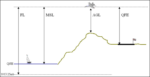
- Distance measurement – vertical (feet – ft)
- Elevations and Altitudes are AMSL
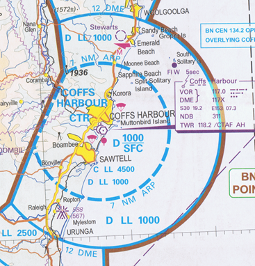
Controlled Airspace & Reading Charts
Controlled Airspace
Airspace of defined dimensions within which air traffic control services are provided. There are two primary definitions of these types of airspace:
- Control Zones (CTR)
- Control Area (CTA)
Control Zone
A Control Zone (CTR) is:
- Controlled airspace extending upwards from the surface of the earth to the specified upper limit.
- Surround controlled airports (civil & military).
- Are active during the hours of control tower operation at the airport as published in ERSA or as varied by NOTAM.
- Outside tower hours, when the CTR is not active, the airspace is reclassified Class G (i.e. outside controlled airspace).
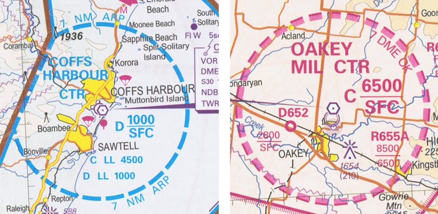
Control Area
A Control Area (CTA) is:
- Controlled airspace extending upwards from a specified limit above the earth (e.g. D LL 1000)
- Designated Class A, D, C or E
- Normally operate continuously
- NOTAM or AIP SUP can create, activate or amend CTA to meet temporary requirements
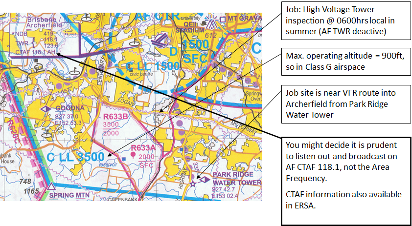
Keeping Outside of CTA
Hypsometric Tint highest elevation (AMSL)
+
400 ft max UAV operating height (AGL)
=
Altitude of operations (AMSL)
How to calculate maximum AMSL for UAV operations to avoid CTA.
Is this < or > CTA LL in the area?
Exercise: PSN S 27o 26’ E 152o 57.5’ (in vicinity of Enoggera)
Airspace Classification
Australian Airspace Policy Statement 2015
This Statement is the Australian Airspace Policy Statement 2015.
Section 4:
The AAPS is made pursuant to Part 2 of the Airspace Act 2007. The AAPS provides guidance to the Civil Aviation Safety Authority (CASA), as the airspace regulator, on the administration of airspace as a national resource. The AAPS is also intended to provide guidance for the aviation industry and other aviation agenciesSection 9:
Purpose of the AAPS (2015)
Airspace administration in Australia is generally aligned with the International Civil Aviation Organization (ICAO) prescribed airspace classes and associated levels of service as set out in Annex 11 to the Convention on International Civil Aviation (1944) (Chicago Convention). Differences to the ICAO classes of airspace in Australia are notified to ICAO and listed in the Australian Aeronautical Information Publication (AIP).
Airspace Classes Used in Australian-Administered Airspace
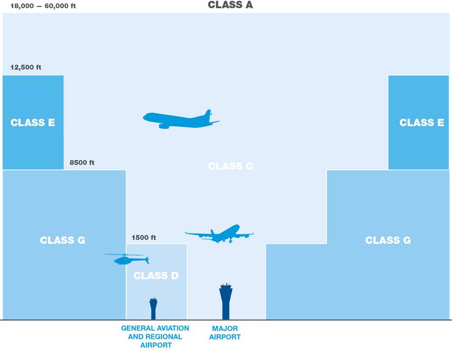
- Class A:
- IFR (instrument flight rules) flights only are permitted. All flights are provided with an Air Traffic Control (ATC) service and are separated from each other.
- Class B:
- IFR and VFR (visual flight rules) flights are permitted.
- All flights are provided with ATC service and are separated from each other.
- This class is not used at present in Australian-administered airspace.
- Class C:
- IFR and VFR flights are permitted.
- IFR flights are provided with an ATC service and are separated from both IFR and VFR flights.
- VFR flights are provided with an ATC service for separation from IFR flights and traffic information on other VFR flights.
- Class D:
- IFR and VFR flights are permitted and all flights are provided with an ATC service.
- IFR flights are separated from other IFR flights and are provided with traffic information on all VFR flights.
- VFR flights are provided with traffic information.
- Class E:
- IFR and VFR flights are permitted.
- IFR flights are provided with an ATC service and are separated from other IFR flights and receive traffic information on VFR flights as far as is practicable.
- VFR flights are provided with a flight information service, which includes traffic information, as far as is practicable.
- Class E:
- IFR and VFR flights are permitted.
- All participating IFR flights receive an air traffic advisory service and all flights receive a flight information service if requested.
- This class is not used at present in Australian-administered airspace.
- Class G:
- IFR and VFR flights are permitted and do not require an airways clearance.
- IFR flights must communicate with air traffic control and receive traffic information on other IFR flights and a flight information service.
- VFR flights receive a flight information service if requested:
- North of 65°S this flight information service includes directed traffic information to IFR flights on other IFR flights and known VFR flights.
Prohibited, Restricted and Danger Areas
Australia has adopted the ICAO designations described in Annex 15, Chapter 2, of the Chicago Convention for accommodating activities that may be incompatible with routine flying operations, i.e. Prohibited, Restricted and Danger Areas.
These areas and the circumstances in which they can be declared are described at Regulation 6 of the Airspace Regulations 2007. This is consistent with the relevant ICAO documentation.
- Prohibited Areas (P):
- An airspace of defined dimensions within which the flight of aircraft is prohibited.
- CASA must not declare airspace to be a Prohibited Area unless, in the opinion of CASA, it is necessary for reasons of military necessity to prohibit the flight of aircraft over the area.
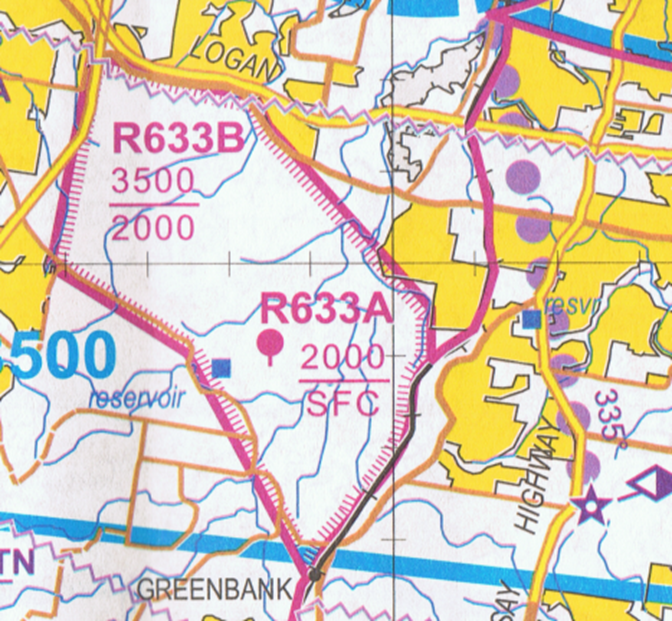
- Restricted Areas (R):
- An airspace of defined dimensions within which the flight of aircraft is restricted in accordance with certain specified conditions.
- CASR 101.065
- CASA must not declare airspace to be a Restricted Area unless, in the opinion of CASA, it is necessary in the interests of public safety, including:
- The safety of aircraft in flight
- The protection of the environment or security
- To restrict the flight of aircraft over the area to aircraft flown in accordance with specified conditions.
- Examples include:
- Bushfires
- Major crime scenes
- Large public events
- Danger Areas (D):
- An airspace of defined dimensions within which activities dangerous to the flight of aircraft may exist at specified times.
- CASA must not declare airspace to be a Danger Area unless, in the opinion of CASA, there exists within or over the area an activity that is a potential danger to aircraft flying over the area.
Up-To-Date Information
Notice to Airmen
A Notice to Airmen (NOTAM) is a notice distributed by means of telecommunications containing information concerning the establishment, condition or change in any aeronautical facility, service, procedure or hazard, the timely knowledge of which is essential to personnel concerned with flight operations.
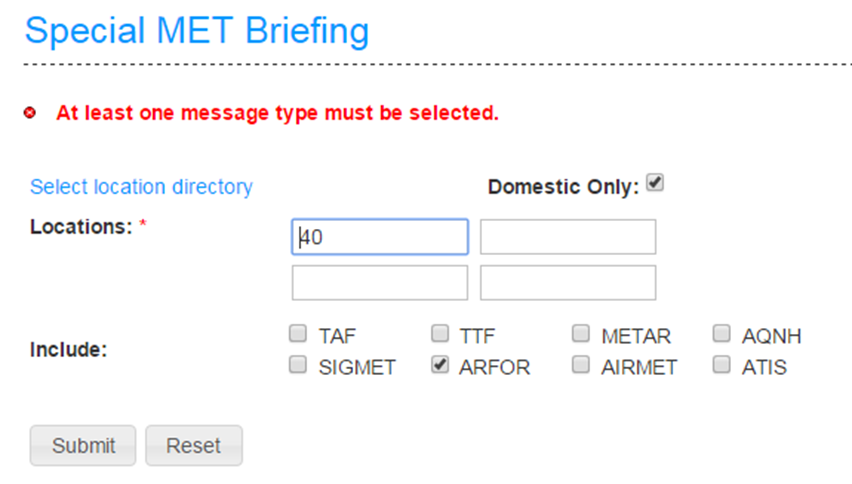
Area Briefing:
- Aerodrome NOTAM.
- Prohibited, Restricted, Danger Area NOTAM (individual & group).
- Flight Information Region (FIR) NOTAM.
- Head Office NOTAM.
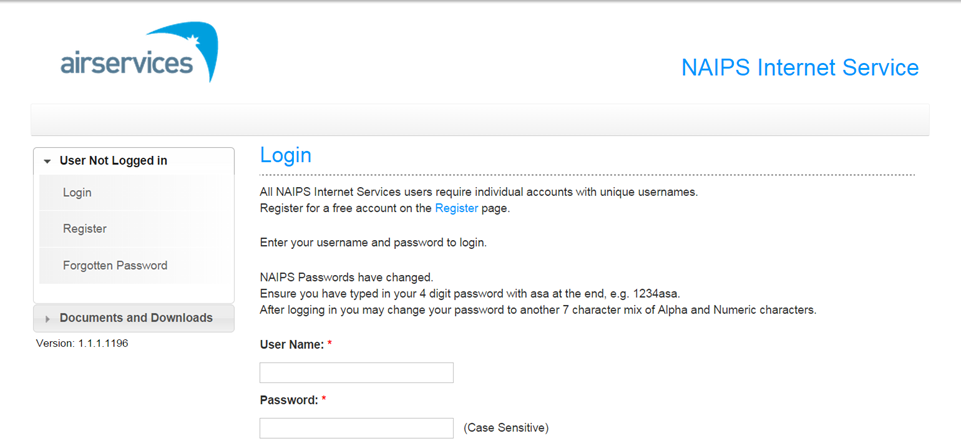
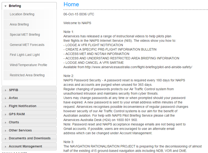
Airservices provide a free registration to access NOTAMs: https://www.airservicesaustralia.com/naips/Account/Logon
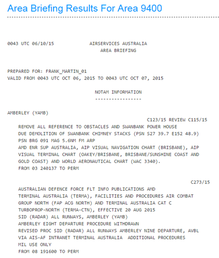
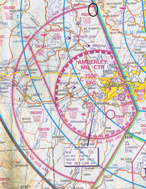
Example NOTAM for RAAF Base Amberley (YAMB)
NOTAM INFORMATION
-----------------
AMBERLEY (YAMB)
B432/20
CTR ACT
TIMES MAY VARY AT SHORT NOTICE. PILOTS RESPONSIBILITY TO CK AND MNT
STS AND OBTAIN BRIEFINGS FOR AMX, AEX, AWX AND EVX.
SFC TO 8500FT AMSL
FROM 08 052140 TO 08 061300
C312/20
TWY J NOT AVBL
DUE PARKED ACFT
FROM 08 060400 TO 08 061200
C311/20 REVIEW C300/20
RWY 15/33 NOT AVBL DUE WIP
MEN AND EQPT WILL VACATE WITH 30MIN PN. CTC WORKS SAFETY OFFICER CS
'CABLE PARTY' ON COMMON TFC ADVISORY FREQ (CTAF) 118.3 OR
TEL: 0418 446 459
FROM 08 051000 TO 08 081830
2008051000 TO 2008051830
2008061000 TO 2008061830
2008071000 TO 2008071830
2008081000 TO 2008081830
C290/20 REVIEW C232/20
AIR MOVEMENT SECTION (AMS) MIL FREQ 361.6
DEGRADED SERVICE - RECEIVE ONLY
FROM 07 150344 TO 10 150200 EST
B280/20
FLIGHT PROCEDURES AMD
DELETE PARAGRAPH 1.
AMD EN ROUTE SUPPLEMENT AUSTRALIA (ERSA)
FROM 05 072336 TO PERM
C279/20 REVIEW C135/20
AUSTRALIAN DEFENCE FORCE FLT INFO PUBLICATIONS AMD
TERMINAL AUSTRALIA (TERMA), FACILITIES AND PROCEDURES AIR COMBAT
GROUP NORTH (FAP ACG NORTH)
ILS-Y RWY 15
LOC-Y RWY 15
TACAN RWY 15
TACAN RWY 33
RNAV (GNSS) RWY 04
RNAV (GNSS) RWY 15
RNAV (GNSS) RWY 33
CIRCLING MINIMA CAT A 830 (739) -2000
DUE CRANE OPS PUBLISHED BY SEPARATE NOTAM. MIL USE ONLY
FROM 07 082030 TO 10 010830 EST
DAILY 2030/0830
C278/20 REVIEW C131/20
OBST CRANE 427FT AMSL
BRG 118 MAG 2.02NM FM ARP
INFRINGES INNER HORIZONTAL SFC BY 197FT
FROM 07 082030 TO 10 010830 EST
DAILY 2030/0830
C267/20 REVIEW C266/20
TWY B NOT AVBL
TWY H NOT AVBL
FROM 06 290500 TO 08 310500 EST
C216/20
RADIO NAVIGATION AND LANDING AIDS AMD
TACAN 'AMB' 108.1/CH18X 273829.4S 1524258.0E
AMD EN ROUTE SUPPLEMENT AUSTRALIA
FROM 05 260549 TO PERM
C215/20
AMEND ALL TACAN NAV CHECK BOARDS: AMB TACAN OPERATIONAL CHANNEL IS
18X
AZIMUTH & DISTANCE DATA CORRECTIONS:
TWY B THR RWY04: 225 DEG 0.5NM
TWY A1 THR RWY33: 177 DEG 0.4NM
TWY C THR RWY33: 148 DEG 0.3NM
TWY C THR RWY22: 036 DEG 0.4NM
TWY D THR RWY22: 016 DEG 0.4NM
TWY A4 THR RWY15: 318 DEG 1.3NM
AZM & DISTANCE DATA TAKEN AT HOLD POINT EXC FOR TWY A4 TAKEN AT TACAN
MARKING
FROM 05 260538 TO 08 260700 EST
C212/20 REVIEW C189/20
RADIO NAVIGATION AND LANDING AIDS AMD
ADD NOTE ASSOCIATED WITH TACAN 'AMB' 108.1/18X
POSSIBLE BEARING UNLOCKS OUTSIDE 20TAC IN SECTOR R100-R120 DUE
TERRAIN.
AMD EN ROUTE SUPPLEMENT AUSTRALIA (ERSA)
FROM 05 260517 TO PERM
C211/20
AUSTRALIAN DEFENCE FORCE FLT INFO PUBLICATIONS AMD
TERMINAL AUSTRALIA (TERMA), FACILITIES AND PROCEDURES AIR COMBAT
GROUP NORTH (FAP ACG NORTH)
NAVIGATION AIDS
AMD ALL REFERENCE TO TACAN 'AMB':
108.1/CH18X 273829.4S 1524258.0E
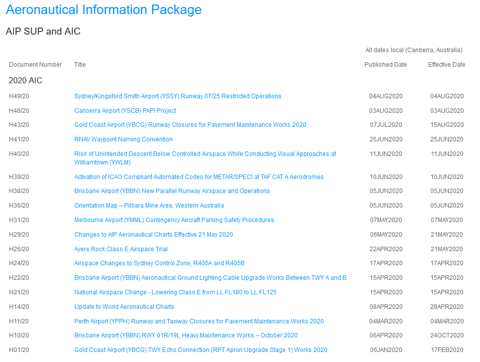
FROM 05 260510 TO PERMAeronautical Information Publication Supplements & Information Circulars
| Aeronautical Information Publication | AIP | A publication issued by or with the authority of a State and containing aeronautical information of a lasting character essential to air navigation. |
| AIP Supplement Military Exercises! | AIP SUP | Temporary changes to the information contained in the AIP which are published by means of special pages. |
| Aeronautical Information Circular | AIC | A notice containing information that does not qualify for the origination of a NOTAM, or for inclusion in the AIP, but which relates to flight safety, air navigation, technical, administrative or legislative matters. |
Airservices provide a free access these publications and information packages:
- Main page: https://www.airservicesaustralia.com/aip/aip.asp
- AIP SUP and AIC: https://www.airservicesaustralia.com/aip/aip.asp?pg=50
Privacy
Privacy from aeronautical operations:
- Governed by local, state, and federal law
- Any tasking must be lawfully commissioned.
- Only data related to the tasking should be collected.
It is your responsibility to ensure any other data collected (which is not related to the tasking) is securely stored or disposed of so as to not end up in the public domain.